 |
| Shape
pot of osc2 wiring |
Pots to replace with
push-pull ones :
- 3 oscillators "shape"
- "reverb mix"
When pulled, the "shape" knob of each oscillator activates the mod.
All 3 oscillators and even "reverb mix" can be controlled alone or together.
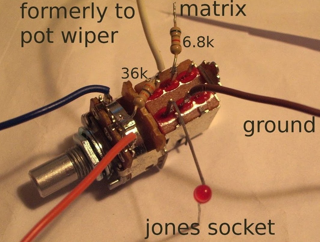
The matrix "m" output is connected to the "E" lugs of the "shape" push-pulls through 6k8 resistors.
Each "D" lug is connected to pot wipers with correspondent resistors that you'll short and take away from the PCB (osc1 : R197 - 68k, osc2 : R226 - 36k and osc3 : R260 - 36k) and to the cable formerly connected to pot wiper.
- 3 oscillators "shape"
- "reverb mix"
When pulled, the "shape" knob of each oscillator activates the mod.
All 3 oscillators and even "reverb mix" can be controlled alone or together.
The matrix "m" output is connected to the "E" lugs of the "shape" push-pulls through 6k8 resistors.
Each "D" lug is connected to pot wipers with correspondent resistors that you'll short and take away from the PCB (osc1 : R197 - 68k, osc2 : R226 - 36k and osc3 : R260 - 36k) and to the cable formerly connected to pot wiper.
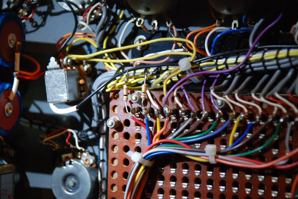 |
| The
"reverb mix" pot
wiring to the
matrix. Original
cable connected with heatshrink to a new one going to the push-pull pot ant then to the reverb circuit (yellow). The mauve one goes to the "shape" pots. |
For the other connections, just respect the original ones when replacing the pot.
Voltage controled filter response
The same technique can be applied to the filter response. Simply connect the matrix "meter" output to the "response" pot wiper, attenuate with a resistor if needed. This "passive" mod works only if the response pot is set high enough to have the filter oscillating, and is much influenced by pins crosstalk, what can give some interesting results.A good way to have a real control of the response is to use an "active" mod. A nice explanation and schematics are available on the Sussex VCS' website.
The "meter" column can be used instead of the "reverb mix", meter has to be deconnected from the matrix when push-pull pot is pulled.
Pot to replace with push-pull one :
- filter "response"