Portabellabz - finest EMS gear service

Expand and preserve your beloved Synthi


Matrix MKI/MKII layout

Some users - including me - think that the MKI matrix layout with separate waveform outputs for oscillators 1 and 2 is more useful.
But the output channels reinjection on MKII matrices can be interesting too, a.o. for feedback loops e.g.

Here's how I modified the matrix in my AKS to allow layout switching between MKII and MKI  (almost MKI indeed, it doesn't move the meter column ;)).

I used 3 common DPDT switches, placed inside the Synthi.
  1. disconnects the output channels connections from lines 1 and 2
  2. selects separate waveforms of osc1 (to rows 1 and 2) or sum of both
  3. selects separate waveforms of osc2 (to rows 3 and 4) or sum of both

matrix
Add a switch between the resitors on the matrix lines 1 and 2 and the wires for the output channels using A/D and B/E lugs, the former cables need to be extended.
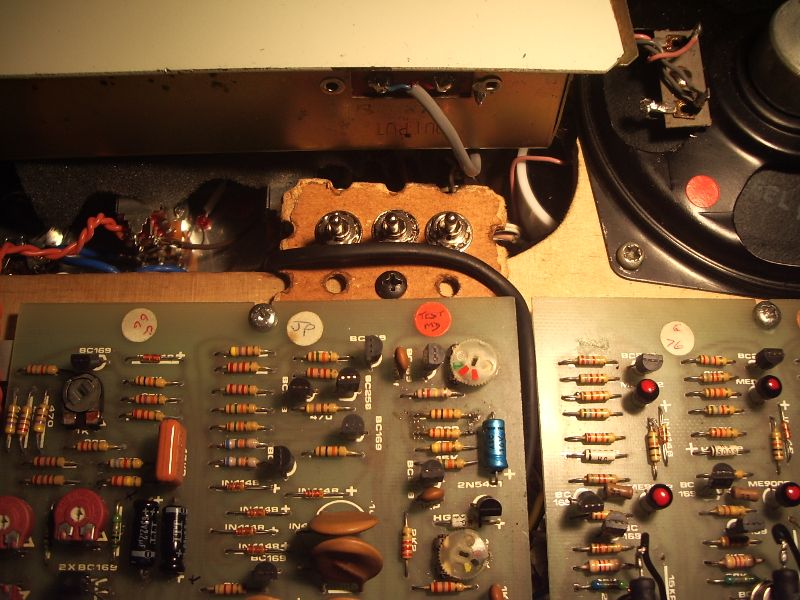
Regarding the oscillators, both waveform level pots are connected through resistors to a (white) cable that goes to the matrix. Disconnect them and connect the (white) cable to the switch's A and D lugs (connect to both to sum both waveforms), the resistors to the B/E lugs and the matrix lines 1 and 2 (3 and 4 for oscillator 2) to the C/F lugs.
Use shielded and grounded cable.

Switches can be placed on a small plate screwed on the speakers wooden frame.

Of course you have to open the Synthi to change the matrix layout, but I don't think is a mod you'll need to switch while playing.


matrix
To use the prestopatch socket with this mod, you'll have to modify its connection on the last lug on the right because is connected to the high level input ch2, not to the matrix line 1. If you don't, oscillator 1's sine wave won't be available on the socket.
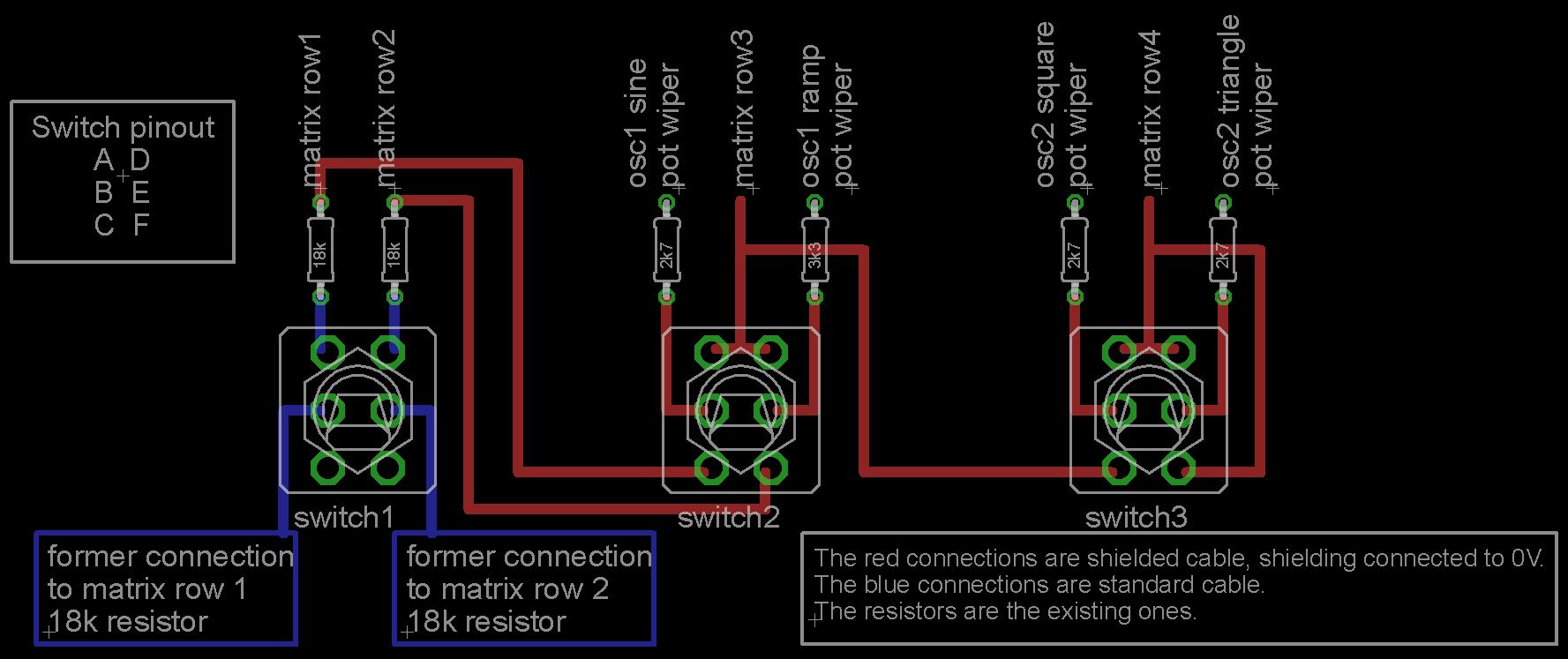
Disconnect the original (yellow) cable and insulate its end. Then connect the matrix line 1 lug to it (white cable on the pic).


No hole
Push-pull pots
Voltage controlled shape and response
Hi/lo range switchable oscillators

Filter 18/24 db
Simple Random Voltage Generator and Sample & Hold

Documents, manuals, dopesheets, links

Filter slew/unslew
Oscillator synchronization
Attack and decay time extension
LEDs
"Synthi 2" interface


Contact

Warning - disclaimer

All modifications are at your own risk and I assume no liability for personal injury or damage to equipment or loss of use caused directly or indirectly by the use of any info shared in these pages.
Although these modifications are quite simple they should only be performed by those experienced in electronics with access to at least a good oscilloscope and frequency meter, some will need a recalibration of the Synthi. Do not attempt otherwise.

EMS PCBs are very fragile,
to avoid damaging the tracks do not use a too hot soldering iron (I set mine to 315°C).


Creative Commons - by-nc-nd 3.0