 An
ultimate sophistication is
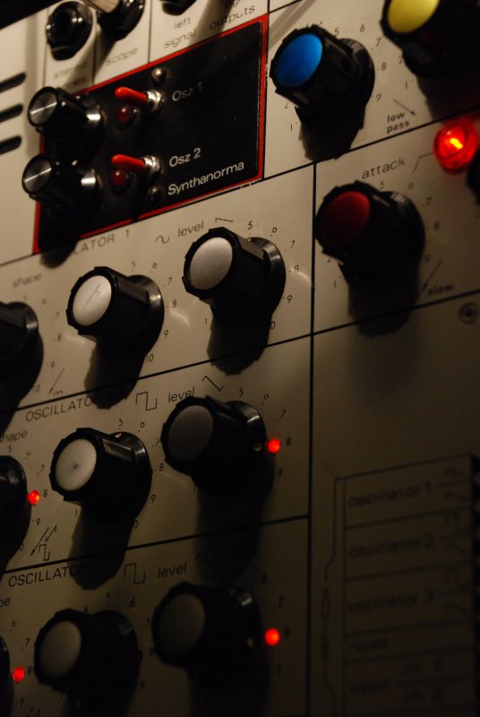
the add of LEDs in the spare
anti-rotation holes left by
the original pots, push-pull
pots are smaller (16 mm).
An
ultimate sophistication is
the add of LEDs in the spare
anti-rotation holes left by
the original pots, push-pull
pots are smaller (16 mm).It looks very nice and is useful in live situation.
3mm common LEDs fit perfectly the holes on my Synthi AKS, but on my Synthi A MKI, I had to slightly widen the holes.
Factory PSUs are strong enough to power about 15 LEDs (about 30mA) with either the +12V or the -9V in standalone.
A total recap of the board A might be useful if it still has the factory blue Erie electrolytic capacitors, in the 60s-70s their life expectancy was about 15 years only...
- MKI PSU :
according to the user's
manual, it delivers an
extra 50mA on both rails
(be careful if you use a DK1 or DK2 keyboard, I don't know this device's consumption, check it).
- MKII PSU : I
couldn't find what power
it delivers but the KS's
power consumption is
600mA on the +12V rail
and 190mA on the -9V
rail.
The +12V rail is probably good for another 100mA, but the heat build-up around the two PSU transistors that are bolted to the Synthi case might be a problem. These are often a source of failure.
It's thus good hooking up the LED's to the -9V rail, it uses the same transistor type as the +12V and delivers about a third of the current.
I did this on my AKS and it works fine with the KS and all the LEDs on.
I suggest making a separate circuit for the LEDs only. Power can be taken from the Jones 8 pins socket ("keyboard").
+12V is on pin 4
-9V is on pin 2
ground is on pin 3
Be careful not to short-circuit these pins.
Add a resistor (about 500 ohms, depending on the LED type you use) on the power cable to the LEDs to avoid overloading them.
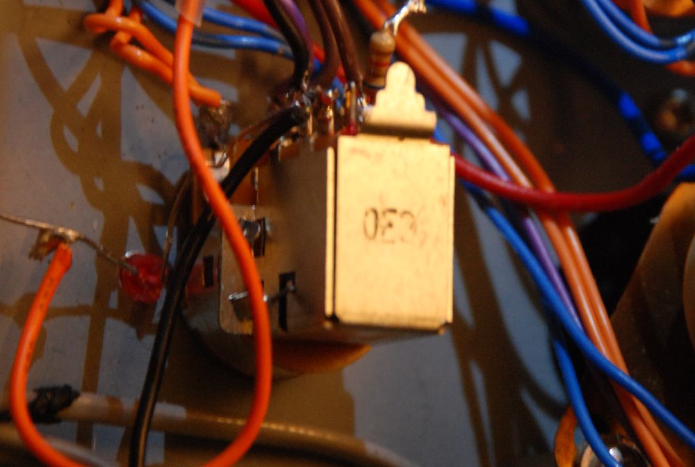 |
| The
orange cable is
connected to the
jones socket, the black one to the ground through the switch. |
Solder the short LED leg (-) to the cable coming from the Jones socket and the other leg (+) to the "B" lug. Connect the "A" lug to ground (available from many places in the Synthi, even often from the pot itself) and fold the legs to put the LED in the hole. It might be good to insulate the legs with heatshrink.
Of course "A" "B" "C" and "D" "E" "F" lug connections on the push-pull's switch can be swapped to facilitate the LED placement according to the hole position.
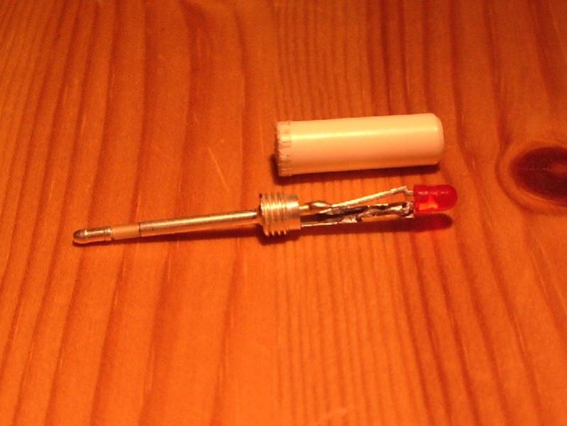 Another
interesting use of LEDs is
to place one in a pin.
Another
interesting use of LEDs is
to place one in a pin. Replace the resistor of a common pin (easier if you shorten the small metal plate) with a LED and cut away the top of the plastic cap. Wire cathode/anodes in opposite ways on the pins so in one case the pin lets in positive voltages, the other is reverse biased. So each would have its own different affect routing bipolar signals around the matrix.