PORTABELLABZ


PCBs for EMS Synthi A / AKS / VCS3


The PCBs come unpopulated and without parts. All modifications are at your own risk and I assume no liability for personal injury or damage to equipment or loss of use caused directly or indirectly by the use of any of the PCBs. Although the installation is quite simple it should only be performed by those experienced in electronics.


Patch matrix buffering

From the factory, the matrix is not buffered.

For example, if you scale a CV to control oscillator 1 and you then want to patch the same CV source to oscillator 2, oscillator 1 will go out of tune when you insert the pin into the row.
The row buffer will prevent this and keep a stable pitch regardless of the number of pins present in the row.

If you now decide to add an extra modulation from another source,  normally the oscillator scaling will go out
when you insert the pin into the column.
The column buffer will prevent this and
keep a stable scaling regardless of the number of pins present in the column.

Buffering the matrix entirely is not essential and affect the Synthi's behaviour and character but some prefer this to achieve true summing and have a more predictable instrument.

Buffering rows 8 and 9 only is very useful when external controllers are used for the pitch. It doesn't alter the instrument's behaviour since the buffers process external signals patched to the input channels.
Buffering a few rows and columns only is useful to keep stable voltage where it's needed : oscillators and filter frequency columns and input channels, joystick, oscillator 3 rows. To buffer the trapezoid row, the polarity control push-pull pot is a more versatile solution.
The buffers on columns work properly with buffered rows only.
To meet each Synhi user's own needs and preference, I offer 2 solutions : modular and full buffering.

Installation procedure and BOM

Modular buffering

Each PCB mount directly to the matrix and need no other support or screw or hole.
No pin resistor value modification is needed.
The mod is 100% reversible.
The PCBs fit both Sealectro and Ghielmetti 621 matrices.

Each small PCB for rows is able to buffer 2 adjacent rows and can be used for 1 only if desired.

The large PCB for columns offers up to 4 buffers directly connected to the oscillator and filter frequency columns. Each buffer is independent, so you can use all 4, or 3, or 2 or even 1 only to match your own needs.


4 columns + 10 rows buffering PCB set shipped untracked : 40 euros


Full buffering

This PCB is not tested in a Synthi yet (I don't want to fully buffer mines)
but works perfect in my EMS 16 x 16 Matrixing Panel and should work as well in a Synthi as are the same circuits as the modular PCBs.
The board mounts to the matrix and needs no other support or screw or hole.
It features a large perfboard to install other circuits.


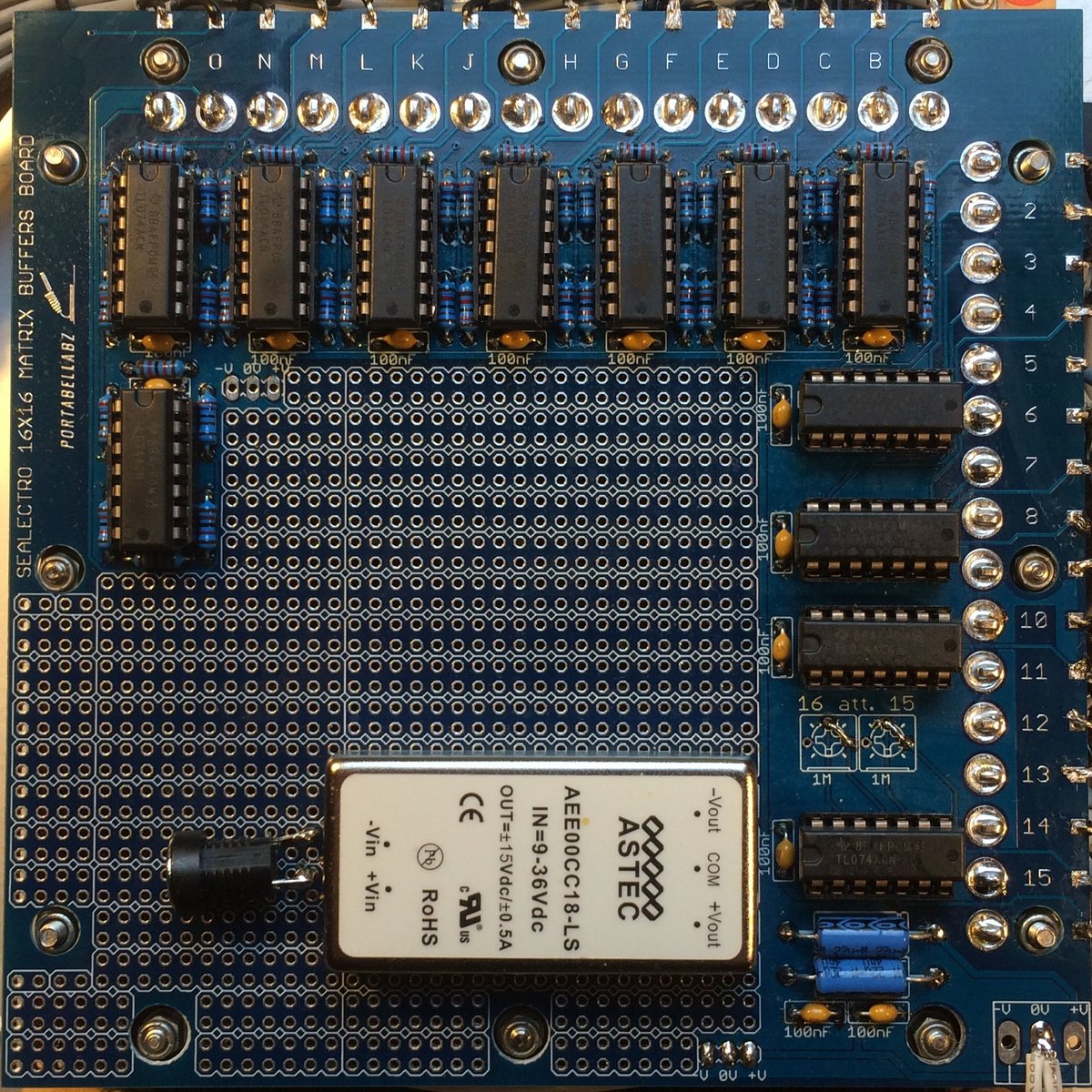
Full buffering PCB shipped untracked : 70 euros


Duophony PCB for D
K1 and Cricklewood keyboards

This PCB is based on the one EMS used to add the DK2's duophony to the monophonic DK1 and Cricklewood keyboards.

The installation is easy and doesn't need any permanent modification or intervention to the original PCB, the pic speaks for itself.
Pin 5 "ch2 sw" goes to the ch2 switch, disconnect the former grey cable, insulate it's end and connect the PCB's "ch2 sw"< in its place.
The schematics and calibration procedure are in the service manual.
The PCB comes with a copy of the original installation notes by EMS.


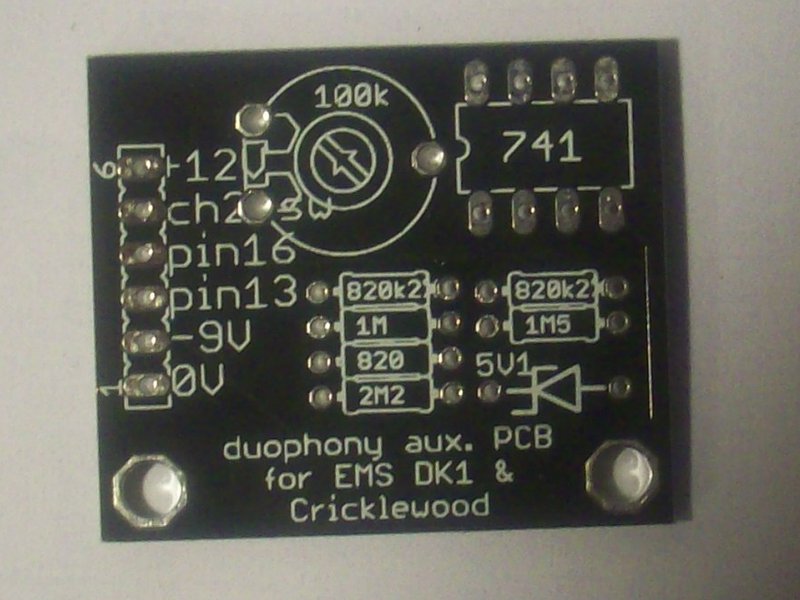
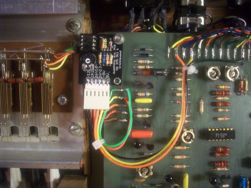
Duophony PCB shipped untracked : 15 euros


MFC6070 replacement PCBs


The MFC6070 reverb driver in the MK2 Synthi A and VCS3 is getting increasingly rare and expensive.
The reverb circuit using it is the less good sounding despite very common.
It's fragile and a frequent cause of reverb issues.

Rather than pay unjustified price for such a crappy part, why not replace it with the better sounding and more reliable MK1 or MK3 driver ? The three circuits are very similar and the MFC6070 can be replaced with a small PCB without any modification of the original traces.

The MFC234 replaces the MFC6070 with the PA234 or GEL234F1 (same part renamed) used in the MK1 units. GE ceased production of this early audio amp IC around 1971, it is thus hard to find today. Many see it as the most desirable output amps and reverb driver in a Synthi or VCS3. It's the essential part of the nice MK1 sound.

The MFC741 replaces the MFC6070 with a 741 and a AC153K/AC176K germanium transistors pair, easier to source than the PA234. This is what I call the "MK3" reverb circuit used in the Synthi A and VCS3 since the late 70s and still today.


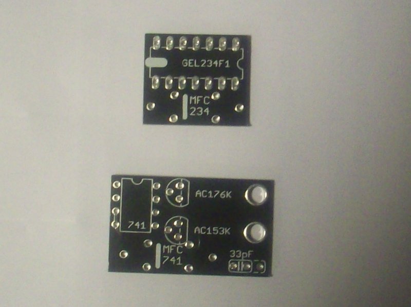
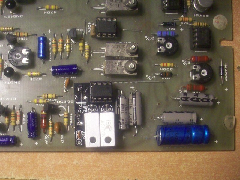
The installation is straightforward and doesn't cause any damage to the original PCB :
  1. remove the 2 resistors and 3V6 zener diode above the MFC6070
  2. replace the 3V6 zener diode with an insulated wire
  3. remove the polystyrene cap to the right of the MFC6070
  4. remove the MFC6070
  5. solder a piece of component leg in the holes of the MFC6070 emplacement, the top right one can remain empty, it's not used and a corner of the AC153K obstructs the hole on the daughter PCB
  6. thread the MFC741 or MFC234 populated PCB onto the component legs
  7. solder and cut the exceeding pieces of component leg

MFC741 PCB shipped untracked : 15 euros

MFC234 PCB shipped untracked : 15 euros