|
The PanADSR for EMS Synthi
A / AKS / VCS3
New Portabellabz expansion card featuring a versatile
looping VC ADSR with panning function.
The card simply plugs directly into the 8 pins Jones
"keyboard" socket and is powered by the Synthi, no
cables no connector, it's plug and play, easy and hassle
free.
For use with a VCS3, the Jones
plug can be mounted onto the top side of the PCB but an
adapted umbilical cable with swapped connections is
requested, the standard cable won't work.
Warning : the card's power consumption is too high for
MK1 units
An extra PSU can be added to MK1 units to power a
KS / TKS keyboard and the Portabellabz expansion cards,
here are the details.
Users manual
A pre-built PanADSR costs 380EUR or 500EUR with
4 banana-pin cables.
VAT and shipping excl.
Contact me
to order.
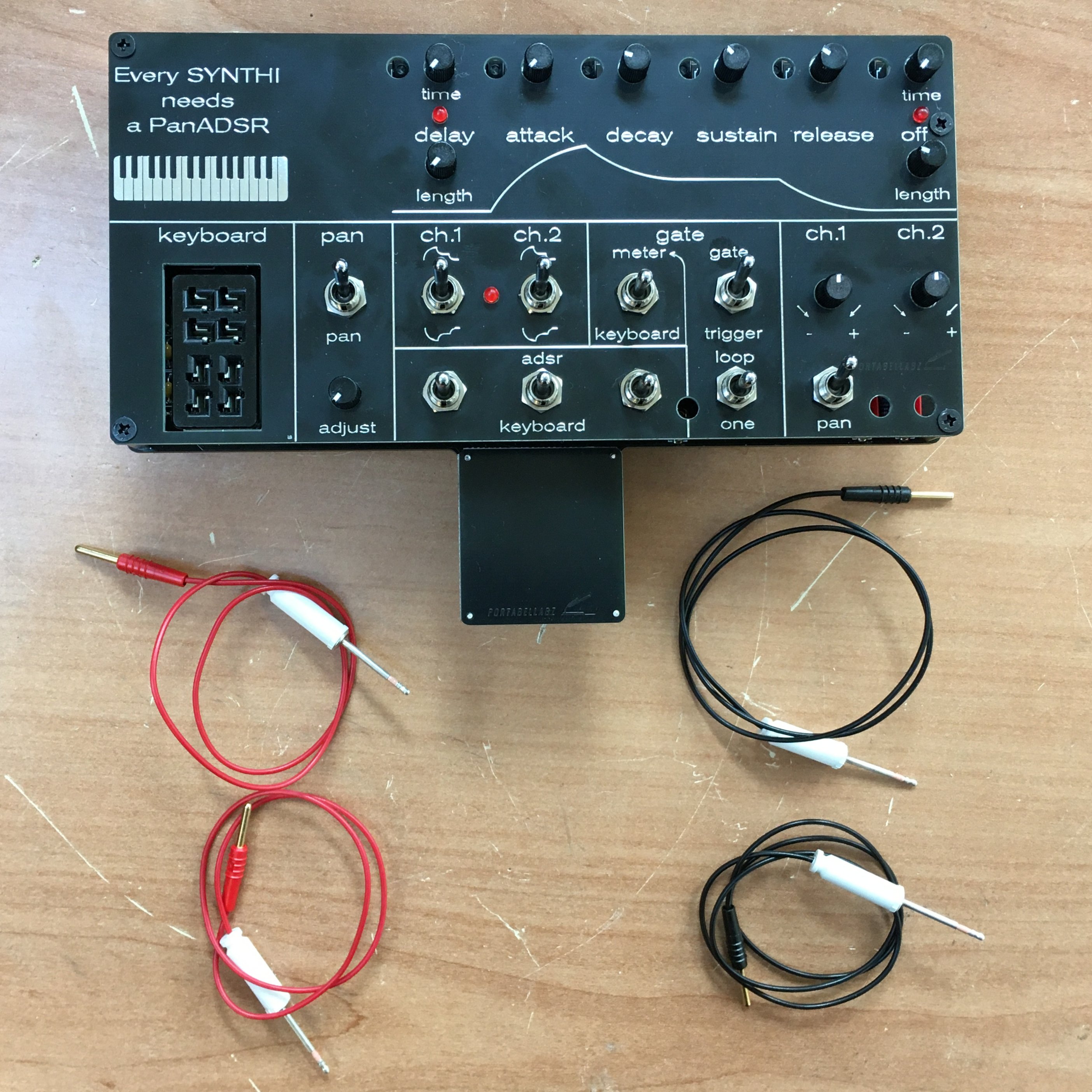
Looping VC ADSR
envelope generator
Based on the AS3310 chip
http://www.alfarzpp.lv/eng/sc/AS3310.pdf
Delay : time delays the begin of the ADSR cycle
by 0 to 10S after a gate signal is applied to the
keyboard Jones socket or the gate in minijack.
length sets the pulse length.
the mini slide switch on the left side selects 2S
(bottom) or 10S (top) maximum delay time.
the LED monitors the pulse.
Attack, decay, sustain, release : standard ADSR
settings
Off : time delays the self-retriggering of the
ADSR after the end of cycle by up 0 to 10S for the
loop mode (see below).
length sets
the retrigger pulse length.
the LED
monitors the pulse and also lights up when the loop
mode is not enabled.
Each setting of the ADSR can be voltage controlled
from the matrix.
Keyboard Jones socket
For EMS controller (KS, TKS, DK1, DK2, Cricklewood…),
Portabellabz CV/Gate Card, Digitana interface or
Jones/minijack cable.
Pan
Signal panning between the 2 output channels
Ch.1 – Ch.2 switches
Adjust the polarity of the ADSR signal routed to the
Synthi’s input channels and to the patchable outputs
(see below).
ADSR / keyboard switches
Route either the ADSR or keyboard Jones socket to the
Synthi’s ch.1, ch.2 and gate inputs.
Gate switches
Meter / keyboard : fires the ADSR either from the
meter column, banana socket and Synthi’s scope jack
socket (top) or keyboard (bottom), central position is
off.
Banana socket : patch with a 2mm banana – pin
cable to fire the ADSR from the matrix when the meter
/ keyboard switch is in its top position.
Gate / trigger switch : sets the ADSR’s sustained
or transient response to the gate signals.
Loop / one switch : enables the looping mode
(top) and fires the ADSR manually (bottom –
momentary), central position stops the looping. To
start the ADSR looping without external signal, switch
to bottom and then immediately to top.
Ch.1 and ch.2 pots
Patchable outputs to the matrix.
Patch with a 2mm banana – pin cable to a red socket
route the ADSR signal via the matrix.
Adjust the amplitude and polarity with the
attenuverter pot.
2mm banana – pin cables
The optional supplied cables are 33cm red to patch the
patchable outputs to the matrix (red sockets) and
45cm black to patch signals from the matrix to the CV
or gate inputs (black sockets).
2mm banana sockets
The sockets can host a banana cable on their top, side
and bottom.
The black sockets are inputs intended to accept one
signal at a time only.
The red sockets are outputs. Several cables can be
stacked to these in order to route the signal to
different patch points of the matrix.
Gate in mini jack socket
Patch external signal between +2.4V and +12V here to
fire the ADSR.
Handle support
Lock the Spartanite case's handle to the back of the
card for better stability.
|